![]()
![]()
![]()
![]()
![]()
![]()
![]()
![]()
![]()
![]()
![]()
![]()
![]()
Locost Build - progress report (latest at top of page)
4th April 2002
I didn't do a lot of work over the winter, due to cold weather, pressure of work, and Locost Limited going bust owing me £280 for parts I had ordered. However, on Easter Monday I finally restarted work. I finished welding up one side of the rear suspension, but I wasn't happy with the end result, in terms of strength or geometry. So I fired up the big disc cutter and chopped out all the suspension and differential mounts, and have now started welding in new metal as per the book, to accept a live rear axle, which is what I should have done two years ago. In the interests of actually getting the car on the road some time this decade, I have decided to go with Ford components front and rear, which means the link between my Locost and the Triumph Vitesse I started with is now almost completely broken. Only the wiring loom, instruments and a couple of small components remain from the original plan.
The next big push should come in a couple of weeks time, when I will take a week off work and try to get the suspension done. I am a bit short of funds, so I have put my V8 Land Rover up for sale on eBay - how much work I can do on the Locost this month will depend on whether anyone buys the Landie.
1st December 2001
As planned, I took two weeks off work to spend on the Locost. I made a bit of a slow start, as I had just bought a Jack Russell puppy and didn't want to leave him alone for any length of time at first, but I finally cleared all the junk out of the garage, broke out the big power tools and set to work. The target for the fortnight was to get the car on its wheels, with the engine and transmission installed, steering connected, dashboard and electrics fitted and the scuttle panel in place. However, I could not start on the front suspension, as I was waiting for parts that I had ordered.
Steering and pedals
So instead I set to work fitting the pedal boxes (Vitesse items, which needed a little trimming), welded up the remaining panelling around the bulkhead, and then turned my attention to the steering column. I am using a Fiesta column which has a disengagement device in it, but as it is designed to connect direct to a steering rack, I needed a bearing support for the lower column shaft which would secure it to the bulkhead. The shaft measured up at 22mm, so off I went to my local bearing supplier to see if they had anything suitable. The closest they could get was 25mm, but by sleeving the column shaft with steel tube, I was able to use this. I mounted it on a bracket of U section steel, bolted to the bulkhead. It really needs a reinforcing plate in this area, as the bulkhead panel flexes slightly as you turn the wheel (due to the disengagement device causing the lower shaft to try to run out of true), but once it is beefed up it should be fine. Then all I need to do is extend the coupling shaft between the rack and column and I will have an SVA compliant steering system.
Steering column bearing, pedal boxes (ex Vitesse) and scuttle in position.
Dashboard and scuttle
Having finished the bulkhead welding I turned my attention to the dashboard. I had earlier acquired a scuttle panel from a racing Caterham Seven, but this was about two inches too narrow for the Locost chassis, so I carefully cut it down the middle, and then spliced the two halves together with pop riveted sheets of galvanised steel (the first thing that came to hand). I will worry later about filling the join properly. Having fettled the widened scuttle so that it fitted the frame properly, I got a big sheet of card and marked out the shape I thought the dash panel should be. Through repeated trial fitting and trimming bits off the edge, I eventually got it to a shape which fitted neatly around the scuttle panel and steering column shroud. This shape was then transferred to a sheet of 6mm MDF which was cut to shape with a jigsaw, then trimmed carefully until it was a perfect fit. The plan is to make the dash from two sheets of MDF glued together and covered with vinyl. That way I can easily recess the old-fashioned Triumph Vitesse instruments into the dash to meet SVA requirements. For the moment though I just made the inner sheet, carefully marked and cut out the holes for the instruments, then fitted them in place (once I had found all the mounting clamps and nuts, which had fallen off and disappeared).
Now I needed to make up a framework to support the dash. This was made from a piece of ¾ inch round steel tube, carefully bent to shape and welded at each end to a length of one inch square tube, which was welded to the chassis top rail. Mounting brackets were made up for the dash panel and scuttle top, and the dash was bolted in place to check that everything fitted OK. I still have to solve the problem of where to put the switches (fog light, hazards and heater fan) - I suspect that if I mount them on the dash, I won't be able to reach them with the seatbelt in place. Also I want the mounting to look pretty, but that can wait for now.
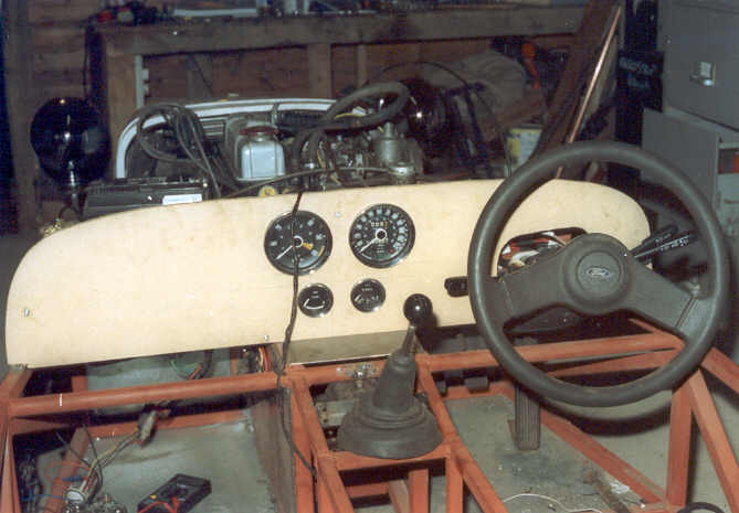
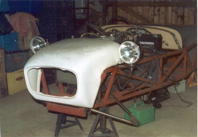
Instrument panel in place. I plan to fit a glovebox on the passenger side, and to fit a switch panel (heater, fog lamp, hazard flashers) between the instruments and steering column.
Exciting noisy stuff
Next job was to crane the engine and gearbox into position and start bolting the engine ancillaries in place. I dug out the manifolds, water pump and starter from the big pile of bits in the corner, bolted it all together, then lashed up a temporary set of electrics consisting of ignition coil, starter solenoid (controlled by the ignition switch on the steering column) and an old trailer sidelight wired up as an oil pressure lamp. A choke control was fitted to the dashboard, and after a lot of time spent cleaning corroded contacts, I finally persuaded the starter to operate. Excitement mounted as with trembling hands I connected a length of fuel pipe to the lift pump, stuck the other end in a can of petrol, and used the priming lever to fill the float chambers of the twin SU carbs. The starter turned the engine over slowly at first, then there was a big puff of smoke from the open exhaust manifold stub, and after a couple more turns the engine burst into (very noisy) life. I let it idle on the choke until the fuel in the float chambers was all gone, then went into the kitchen for a large celebratory mug of tea. The Beast runs!
Plumbing
Of course, if I wanted to hear the engine run properly I would have to do something about the lack of cooling and exhaust systems. Just to be different, I have decided to go for an underfloor-mounted exhaust (as per early Lotus Seven) rather than the side mounted system that everyone else uses. This will reduce ground clearance a bit (but not as much as the sump of that great tall Spitfire motor sticking out underneath), but it fits in well with my general approach, which is to build a car which looks as though it dates from the late 1960s. I picked up a Spitfire MkIV rear exhaust box for £10 at an autojumble - this is a transverse mounted oval box which sits very neatly under the frame behind the rear axle. Careful study of old Triumph parts books revealed that the Spitfire front pipe was almost perfectly straight from front to back, and I wondered whether I might be able to use it pretty much unmodified, but it needed shortening, and it bends down at the back, so I will have to cut and weld both the downpipe and silencer inlet pipe, otherwise the ground clearance will be even worse than an old Austin Healey 3000. However, it isn't far off right even now. As I haven't finished making up the rear frame yet, I just lashed the silencer into place with old U bolts and jubilee clips for the time being.
Next problem was the cooling system. I had bought a Nissan Micra radiator, intending to mount it inside the nosecone where most Locost builders fit their radiators. However, I could not see any easy way of getting this to work, so as to give enough clearance for the radiator cap and cooling fan. No doubt others have managed to use the Micra radiator, but I was stumped. Then I had a flash of inspiration. Was there enough room to mount the radiator in front of the engine, above the steering rack? Yes, there was! Mountings were quickly and easily fabricated, and the electric fan was junked. There wasn't enough room for it, but the radiator was now close enough to the engine to be able to use the Spitfire mechanical fan instead. Not as efficient, but much simpler, and well in keeping with the build philosophy.
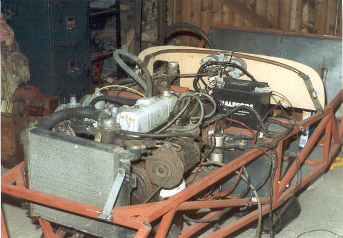
Engine in position - plumbed in, wired up and ready to go.
Anyone who has played around with engine installations will know that cooling hoses can be one of the most difficult areas to get right. In my case, the top and bottom hose stubs on the Micra radiator were on the wrong side for the Spitfire engine. The top hose was easily sorted out - I turned the thermostat housing through 180 degrees, then used a long flexible hose available from Halfords (they sell them as universal radiator hoses). The bottom hose was trickier, as the crank pulley and fanbelt restricted space. I ended up making a cross tube from steel tube with a 90 degree copper elbow fitting (used by plumbers) glued to one end with high strength epoxy. This end was attached to the radiator stub with a very short straight length of hose. At the other end, I made up a bracket to secure the cross pipe to the front of the engine block, keeping it out of the way of the rotating bits. All I then needed was another of Halfords magic flexi hoses to connect the cross tube to the water pump inlet, and I had to trim a bit of metal off the engine mounts to give enough clearance for the hose, and the job was done.
Now for a proper test run. I filled the cooling system with water - it didn't leak! One advantage of my chosen radiator mounting is that the filler cap is above the level of the cylinder head, which solves the filling problems that you can get with a more conventional Locost set up. I took a spare petrol can, drilled a large hole in the middle of the cap to push a length of hose through, and a smaller hole as an air vent. This was my temporary petrol tank. Ignition on, and the motor fired up on the first turn of the starter. On two cylinders. Arse. Had I accidentally drawn dirt into one of the carbs? I had a look in the float chambers - plenty of petrol (and no dirt) there, and sliding needle SUs aren't terribly prone to blockages anyway. I checked the plug leads, and ensured that I had got the firing order correct. Finally, and running out of ideas, I started it up again, removed the air filter from the rear carb, and lifted the dashpot with a screwdriver, in case there was some dirt in the jet. The missing cylinders immediately returned - problem solved.
I let the engine warm up, blipping the throttle occasionally. As soon as the thermostat opened, water spurted from the housing, but this was cured by nipping up the housing bolts and hose clip. The engine sounded very sweet, with a gruff, British sports-car like bark from the exhaust, but no nasty rattles, leaks or blue smoke. Having paid £450 for it as a recently rebuilt engine, I would have been disappointed to find anything else. The Herald gearbox (an unknown quantity purchased for £25) sounded fine, with no bearing noise. So it looks as though the major mechanicals are sound, and having now run the engine for about an hour in total, I am reasonably confident that the cooling system will be adequate for the job.
Bright sparks
By now I was really on a roll, and decided to tackle one of the more daunting areas, the wiring loom. I had a complete Triumph Vitesse loom, but needed to marry this up to the Ford Fiesta column switchgear. First job was to spend an evening in front of the TV, identifying and marking all the wires in the loom with reference to the wiring diagram in the Haynes manual. The loom turned out to be in very good condition, with no cracking insulation or damaged connectors. The next morning I started by connecting up the instruments (the only 'fixed point' in the electrical system so far) and then laid out the rest of the loom around the frame, to work out how best to position everything else. The control box, fusebox and flasher unit went in the passenger footwell, underneath the battery tray (where they should be nice and dry), and the rest of the loom turned out to fit the engine bay extremely well, with only two wires needing to be extended. I had a wiring diagram for the Fiesta, but it was so hard to read that I gave up and used a multimeter to work out which wire did what. The switchgear was then mated up to the wiring loom using soldered bullet connectors, and with just a couple of small modifications to the loom (changing spade for ring connectors) it all worked out beautifully. I tested it with a couple of test lights and a buzzer, and the only problem I had was a poor earth on the instrument lights (quickly sorted). Oh, and the dynamo doesn't charge, but since the car it came off was last on the road in 1988, I am not all that surprised. Why not fit an alternator? It comes back to that question of period character again. I grew up with old British cars, and that flickering red charge light at idle is as much a part of these vehicles as SU carburettors, Smiths chrome-rimmed instruments and chrome hubcaps. So the dynamo stays, but it will need overhauling.
Working backwards
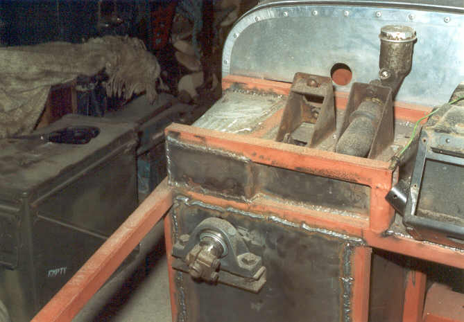
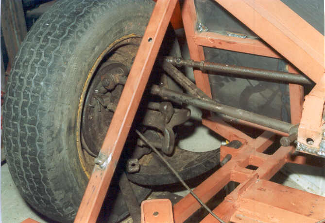
Having concentrated on the front half of the car, I now turned my attention to the rear half. The first job was to sort out the gear change. The Herald box has a very nice remote change, but it needed extending. So I cut the housing and shaft in two. The front half went back on the gearbox, and the rear half was bolted to brackets on the transmission tunnel. I welded a steel tube to connect the two halves of the selector shaft, and now I had a gearchange. Very simple, very positive change. By now my holiday was almost ended, but I wanted to at least make a start on the rear suspension. I had never been happy with the positioning of the upper wishbone brackets, so I cut and welded them into a more geometrically sensible arrangement. Then it was time to start making up the upper wishbones (basically two Vitesse rear radius arms with a diagonal welded between them). At this point things started to go pear shaped. I welded one of the arms on upside-down, so that the inner end bush wasn't parallel with the centre line of the mounting. Not only that, but when I tried to free the threaded adjusters on my four second hand Vitesse radius arms, one came free easily, one sheared off, one bent and one rounded off the adjusting nut. So I need some more radius arms before I can make further progress.
This is a cock-up. The rear wishbone arm is upside-down, so the inner bush isn't parallel to the chassis bracket. Easy enough to fix.
What's next?
The remaining major mechanical jobs are to finish off the rear upper wishbones, extend the rear driveshafts to suit the wider track (another cut 'n' weld job, using thick wall steel tube), sort out the front suspension (currently waiting for parts), extend the lower steering shaft, and rebuild the ex GT6 propshaft using a Herald front yoke in place of the GT6 one. I also need to construct the framework for the rear end of the body, finish modifying the exhaust and fabricate some seat belt mounts. That will be the heavy work finished - once I am totally happy with the mechanical layout, and sure I have welded on enough brackets etc, the car will be fully stripped, the frame primed and painted, and then the build up will start for real. I reckon a target of May 2002 for completion is looking very feasible. I have 11 days holiday over Christmas, so for now I am gathering up all the parts I need for the next big push.
I've done some more work since writing the above report. Here's a sneak preview - looking dangerously like a car. Headlight mounting brackets started life as spring shackles for an Army truck, so they should be strong enough.
1st October 2001
I finally got fed up with having a rusting chassis frame cluttering up my garage and preventing me from working on any of my other vehicles, so I decided to have a major blitz on the Locost and see if I could get some momentum going. The weekend before last I finished shotblasting the chassis and gave it a coat of Jenolite Double Act rust neutralising primer. This stuff sticks beautifully to a shotblasted steel frame, and should keep surface rust at bay until I have the chance to paint the frame. If you are considering buying a shotblaster (click here for details of the one I am using) you may be interested to know that I started by using a very coarse abrasive (copper slag). This was effective enough but slow going. I ran out of grit while still having some blasting left to do, so I decided to try some much finer abrasive (olivene sand) which I had bought to experiment with on aluminium castings. To my amazement, the fine abrasive proved much quicker at derusting steel than the coarse stuff. I suspect it has something to do with using a fairly low blasting pressure (75 psi - my compressor isn't big enough to deliver a continuous pressure any greater than this). If only I had found this out at the start......
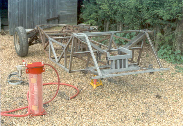
Shotblasting in progress. Only another 10 hours to go.
Anyway, with the frame blasted and primed, the next stage was to fit the bulkheads and floors. For the front and rear bulkheads I used 16 gauge steel sheet - a bit thicker than the book recommends, but these panels are crucial to the rigidity of the frame, so I don't mind a bit of extra weight here. For the floors I used some offcuts of galvanised sheet - 14 gauge under the seats, 18 gauge for the rest. Again, thicker than the book recommends, but if you use thin steel sheet (20 - 22 gauge) it is difficult to stop it distorting horribly when you weld it. My floors are as flat as a coffee table, and they won't rust.... You can weld galvanised sheet if you use a grinder to take the galvanised top layer off the edges. Make sure you wear a dust mask when cutting and cleaning up galvanised sheet, as zinc dust is nasty stuff to get in your lungs, and be extra careful when welding, as the vapour given off by molten zinc is pretty unpleasant as well. In fact, I have a feeling that what I have done is highly dangerous, but it's a bit late to worry about that now. If you are going to mess about with galvanised steel I suggest you research the health implications first (as I didn't do).
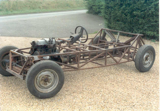
First test fitting of mechanicals. Front suspension design has since changed. That Spitfire motor is a great tall lump considering it's only 1300cc. It sticks out a lot underneath as well.
I also made up a mounting for the pedal boxes and brake/clutch master cylinders. I am using the Vitesse pedal boxes and master cylinder mounts, but will need to find a dual line brake master cylinder and modify the Vitesse mount so that it sits at less of an angle, otherwise the reservoir will come through the top of the bonnet. Having done this, I bolted the pedal boxes and steering column in place, dropped in the seat (Land Rover centre seat - haven't quite worked out how to make it adjustable yet) and then, for the first time, I COULD SIT IN MY SPORTS CAR!!!!! This is one of those crucial moments in the build, like starting the engine for the first time, or fitting all four wheels and being able to roll the car out of the workshop. I sat there for a long time, working out where all the instruments and switchgear would go, and (sad, I admit) operating the steering wheel and pedals, and making 'brumm, brumm' noises with my lips.
Back to reality: I still have a few odd bits of welding to do on the floor and bulkheads, and I also need to panel in the area above the passenger's feet and the sides of the transmission tunnel. By the time that is finished, my specially fabricated lower wishbones (to fit the Vitesse suspension uprights) should be ready, and then I can start the mechanical build in earnest. The plan is to completely assemble the front and rear suspension and steering, fit the engine, gearbox and rear axle, and then work through the car from front to back, fitting all the mechanical and electrical parts and making up brackets as necessary. I will also need to finalise the seat mountings, make up brackets for the safety harnesses and sort out the dashboard and scuttle (I am using an ex-racing Caterham scuttle panel, suitably widened to fit). Then I will turn my attention to the rear end (fuel tank mounts, then the framework for the rear panel). After that I will fit the nosecone, wings, bonnet and bootlid. Once I have every single mechanical and stuctural item bolted on, and I am happy that it will all work, I will completely strip the car and paint the chassis. Then it will be time to panel the sides and rear of the car with aluminium sheet, and start the final build.
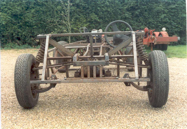
Rear view showing Vitesse-derived IRS. Upper wishbones have yet to be cross-braced. Radius arms and driveshafts missing in this photo. The frame isn't twisted - just an optical illusion.
Timing? I have two weeks holiday coming up in November. I was planning to go away, but then I started thinking about what I could do to the Locost with two full weeks and £750. I reckon that a fortnight of solid work (plus a few evenings and weekends between now and then) will see the project through to the chassis painting stage and possibly beyond. If I can make that sort of progress now, then having the car on the road by next Easter starts to look like a real possibility. There are still plenty of problems to solve: I am not really happy using the Vitesse steering rack for various reasons, I will have to extend the Vitesse rear driveshafts by about an inch because of the wider rear track, and I have a nagging feeling that the Spitfire sump is a bit too deep to give adequate ground clearance. I also need some front top ball joints to fit the Vitesse uprights, which will take some researching. And then there's SVA to worry about; I keep hearing nasty stories about testers failing cars for ridiculous reasons, such as the screw holes in rear light units not having a curved edge to them. Still, I'm in too deep to give up now.
Click here for later progress reports.